
Engineering fits and tolerances are fundamental to mechanical design and manufacturing. They determine whether two components will slide together, locate accurately, require force to assemble, or remain permanently fixed.
Fits and tolerances cause a great deal of anxiety for people asking a machine shop to make a part for them for the very first time. Usually if I ask a first timer whether they can give me a tolerance on a part I get a response such as this:
“Just make it exact so it perfectly fits this part I have in my hand”
Just a couple of points here:
- There is no such thing as exact when it comes to machining. If you accept that the part would not be accurate to an infinite number of zeros after the decimal point the next question would be “so how many zeros are we actually talking about?”
- It follows on that if there is no such thing as exact then your idea and my idea of a perfect fit are subjective and are probably not the same.
- Finally it follows that the measurement you have for your mating part is not exact either. Therefore, even with a tight tolerance, the part I make might not fit yours.
“Fortunately there are established tolerances to work from. Ladies and Gentlemen, may I present H7/g6”
A drawing specification such as Ø25 H7/g6 may look cryptic at first, but it contains a precise definition of the permissible sizes of both components.
The reason the blog post concerns H7/g6, is because it is probably the standard tolerance class we see on drawings for 95% of the enquiries we receive. It is your bread and butter “good” fit.
This guide explains engineering fits and tolerances, how to read ISO tolerance designations, and how classes such as H7 and G6/g6 change with component size.
Important: ISO 286 uses uppercase letters for holes and lowercase letters for shafts. Therefore, H7 is a hole tolerance class, while g6 is a shaft tolerance class. “G6” and “g6” are not interchangeable.
The calculations and tables below are based on the ISO 286 system. For production drawings and contractual requirements, always verify the applicable edition and obtain the standard itself where required.
What are engineering fits and tolerances?
A tolerance is the permitted variation in the size of a manufactured feature.
For example, a 25 mm hole specified as:
25 H7
does not necessarily have to measure exactly 25.000 mm. The H7 designation defines an allowable range around the nominal size.
A fit describes the relationship between two mating features, normally a hole and a shaft.
The three fundamental fit categories are:
- Clearance fit — the hole is always larger than the shaft.
- Transition fit — depending on the actual manufactured sizes, the assembly can have either a small clearance or interference.
- Interference fit — the shaft is always larger than the hole.
The ISO 286 system provides a standardised way of defining these relationships. ISO states that the system is intended for features such as cylinders and two parallel opposite surfaces, and establishes the concepts of tolerance classes, deviations and fits.
How to read an ISO fit designation
An ISO fit designation normally contains a letter and a number.
For example:
H7
- H = position of the tolerance zone
- 7 = tolerance grade, or IT grade
For a shaft:
g6
- g = position of the tolerance zone
- 6 = tolerance grade
The letter therefore tells you where the tolerance zone sits relative to the nominal dimension, while the number determines how wide the tolerance zone is.
ISO 286-1 establishes the basis for this system, while ISO 286-2 provides tables of standard tolerance classes and limit deviations.
Alternative Tolerance Grades (Tighter or Looser Precision)
If H7 is too tight (expensive to machine) or too loose (not accurate enough), you can change the number while keeping the “H” position (zero lower limit for holes):
- H6 / H5: Tighter, higher-precision grades. Use these for extremely accurate spindle bearings or high-end fitments where minimal variation is allowed, though they require precision reaming, grinding, or boring. Gernerally speaking these tolerances add a lot to the cost of a part.
- H8 / H9 / H10 / H11: Looser, more economical grades.
- H8 / H9: Good for general machinery, removable parts, or sliding fits where minor slop is acceptable.
- H11: Very loose; easily achieved with standard drilling or rough manufacturing for pins, bolts, or coarse agricultural linkages
H7 tolerance limits by part size
H7 is one of the most commonly encountered hole tolerance classes in engineering drawings.
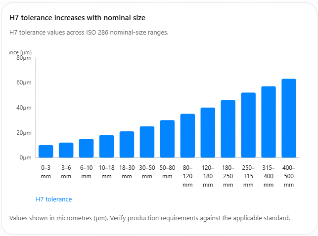
Because H is the hole-basis position, its lower deviation is zero. The IT7 tolerance increases as the nominal size increases.
The following reference table gives the H7 limits in micrometres (µm) and millimetres. The ranges follow the ISO 286 nominal-size bands.
| Nominal size range | H7 lower deviation | H7 upper deviation | H7 tolerance |
|---|---|---|---|
| Over 0–3 mm | 0 µm | +10 µm | 10 µm |
| Over 3–6 mm | 0 µm | +12 µm | 12 µm |
| Over 6–10 mm | 0 µm | +15 µm | 15 µm |
| Over 10–18 mm | 0 µm | +18 µm | 18 µm |
| Over 18–30 mm | 0 µm | +21 µm | 21 µm |
| Over 30–50 mm | 0 µm | +25 µm | 25 µm |
| Over 50–80 mm | 0 µm | +30 µm | 30 µm |
| Over 80–120 mm | 0 µm | +35 µm | 35 µm |
| Over 120–180 mm | 0 µm | +40 µm | 40 µm |
| Over 180–250 mm | 0 µm | +46 µm | 46 µm |
| Over 250–315 mm | 0 µm | +52 µm | 52 µm |
| Over 315–400 mm | 0 µm | +57 µm | 57 µm |
| Over 400–500 mm | 0 µm | +63 µm | 63 µm |
These values illustrate an important engineering principle: an H7 tolerance is not one fixed number. The permitted variation depends on the nominal size.
A point to note here is temperature – ISO 1:2022 states that these measurements are taken at 20 deg’C. With H7/g6, temperature can make a massive difference to the final fit and variation is even more pronounced with certain materials.
What does g6 mean?
The g6 designation is normally used for a shaft.
Unlike H7, the g6 tolerance zone is positioned below the nominal size.
For example, within the 18–30 mm nominal-size range:
- g6 upper deviation = −7 µm
- g6 lower deviation = −20 µm
- total tolerance = 13 µm
Therefore, a nominal 25 mm g6 shaft has limits of:
24.980 to 24.993 mm
The H7 and g6 values combine to produce a clearance fit.
H7/g6 fit chart
The following table combines the H7 hole and g6 shaft limits across common ISO 286 size ranges.
| Nominal size | H7 hole | g6 shaft | Minimum clearance | Maximum clearance |
|---|---|---|---|---|
| 0–3 mm | 0 / +10 µm | −8 / −2 µm | 2 µm | 18 µm |
| 3–6 mm | 0 / +12 µm | −12 / −4 µm | 4 µm | 24 µm |
| 6–10 mm | 0 / +15 µm | −14 / −5 µm | 5 µm | 29 µm |
| 10–18 mm | 0 / +18 µm | −17 / −6 µm | 6 µm | 35 µm |
| 18–30 mm | 0 / +21 µm | −20 / −7 µm | 7 µm | 41 µm |
| 30–50 mm | 0 / +25 µm | −25 / −9 µm | 9 µm | 50 µm |
| 50–80 mm | 0 / +30 µm | −29 / −10 µm | 10 µm | 59 µm |
| 80–120 mm | 0 / +35 µm | −34 / −12 µm | 12 µm | 69 µm |
| 120–180 mm | 0 / +40 µm | −39 / −14 µm | 14 µm | 79 µm |
| 180–250 mm | 0 / +46 µm | −44 / −15 µm | 15 µm | 90 µm |
The clearance values are calculated from the mating limits. For example, the minimum clearance is the smallest hole minus the largest shaft, while maximum clearance is the largest hole minus the smallest shaft.
Worked example: Ø25 H7/g6
Suppose a drawing specifies:
Ø25 H7/g6
The nominal diameter is 25 mm, which falls within the over 18 to 30 mm ISO size range.
H7 hole
The H7 hole has:
- Lower deviation: 0 µm
- Upper deviation: +21 µm
Therefore:
25.000 to 25.021 mm
g6 shaft
The g6 shaft has:
- Upper deviation: −7 µm
- Lower deviation: −20 µm
Therefore:
24.980 to 24.993 mm
Minimum clearance
The tightest combination is:
25.000 − 24.993 = 0.007 mm
or:
7 µm
Maximum clearance
The loosest combination is:
25.021 − 24.980 = 0.041 mm
or:
41 µm
Therefore:
Ø25 H7/g6 produces a diametral clearance of 0.007–0.041 mm.
These limits agree with published ISO 286 reference calculations for the 18–30 mm size range.
Why does the tolerance change with part size?
ISO tolerance grades are based on standard tolerance units that vary with the basic size.
Consequently, an H7 tolerance applied to a small component is tighter in absolute terms than H7 applied to a much larger component.
For example:
| Nominal size | H7 tolerance |
|---|---|
| 5 mm | 12 µm |
| 10 mm | 15 µm |
| 25 mm | 21 µm |
| 50 mm | 25 µm |
| 100 mm | 35 µm |
| 200 mm | 46 µm |
| 400 mm | 57 µm |
This is why a drawing must specify the nominal size as well as the tolerance class. Simply stating “H7” does not tell a manufacturer the absolute limits without knowing the basic size.
Clearance, transition and interference fits
Engineering fits can be understood by comparing the two tolerance zones.
Clearance fit
There is always space between the shaft and hole.
Typical applications can include sliding components, rotating components and assemblies requiring free movement.
Transition fit
Depending on the actual manufactured dimensions, the result may be a small clearance or a small interference.
Transition fits are commonly used where accurate location is important but permanent assembly is not necessarily required.
Interference fit
The shaft is larger than the hole throughout the permitted size ranges.
Assembly may require pressing, heating, cooling or another controlled process.
H7, H6, G6 and g6: don’t confuse the letters
One common source of errors is mixing uppercase and lowercase ISO designations.
| Designation | Feature | Meaning |
|---|---|---|
| H7 | Hole | H fundamental deviation + IT7 |
| H6 | Hole | H fundamental deviation + IT6 |
| G6 | Hole | G fundamental deviation + IT6 |
| g6 | Shaft | g fundamental deviation + IT6 |
| h6 | Shaft | h fundamental deviation + IT6 |
| p6 | Shaft | p fundamental deviation + IT6 |
The case matters.
For example:
- H7 = hole
- h7 = shaft
- G6 = hole
- g6 = shaft
ISO 286’s terminology specifically uses “hole” and “shaft” for the internal and external cylindrical features in the fit system.
What is G6?
G6 is a hole tolerance class, not the same thing as g6.
The uppercase G positions the hole tolerance zone relative to the nominal dimension, while 6 specifies IT6.
The distinction is particularly important when interpreting technical drawings or converting between hole-basis and shaft-basis systems.
For practical engineering work, do not assume that changing the case of the letter produces the same tolerance in the opposite direction. The fundamental deviations for the different letters are defined separately by ISO 286.
Why H7 is so widely used
The H hole position places the lower limit of the hole at the basic size.
That makes it convenient to manufacture a range of fits by changing the shaft tolerance.
For example, a designer can keep the hole at H7 and select different shaft classes depending on the required assembly condition.
Conceptually:
| Hole | Shaft | General fit relationship |
|---|---|---|
| H7 | g6 | Clearance |
| H7 | h6 | Clearance with zero minimum clearance |
| H7 | k6 | Transition region |
| H7 | m6 | Transition/interference region |
| H7 | p6 | Interference |
The exact limits must be calculated from the applicable size range and ISO tables rather than inferred solely from the names. Published ISO 286 reference tables provide the corresponding deviations.
How to calculate an engineering fit
The calculation process is straightforward.
Step 1: Identify the nominal size
For example:
Ø25 mm
Step 2: Identify the hole tolerance
For:
25 H7
look up the H7 deviations for the 18–30 mm size range.
Step 3: Identify the shaft tolerance
For:
25 g6
look up the g6 deviations for the same basic-size range.
Step 4: Calculate the four limits
Determine:
- Minimum hole
- Maximum hole
- Minimum shaft
- Maximum shaft
Step 5: Calculate clearance or interference
For a clearance fit:
Minimum clearance = minimum hole − maximum shaft
Maximum clearance = maximum hole − minimum shaft
If the result is negative, the corresponding condition represents interference rather than clearance.
Engineering fits and manufacturing accuracy
Selecting a tighter tolerance is not automatically better.
A very tight tolerance can require:
- More accurate machining
- More expensive inspection equipment
- Additional finishing operations
- Better temperature control
- More capable production processes
- More stringent quality control
For this reason, tolerance selection should be driven by the functional requirement of the assembly.
If a shaft simply needs to rotate freely, an unnecessarily tight fit may add cost without improving performance.
Conversely, if a component needs accurate positioning, excessive clearance could produce unwanted movement.
The objective is therefore not simply to specify the smallest possible tolerance. It is to specify a tolerance that is appropriate for the function, manufacturing process and inspection method.
ISO standards for engineering tolerances
The principal standards to consult include:
ISO 286-1
ISO 286-1:2010 — Basis of tolerances, deviations and fits
ISO 286-1 establishes the ISO code system for tolerances on linear sizes and defines the concepts behind tolerance classes, deviations and fits. ISO currently lists the 2010 edition as confirmed and current.
ISO 286-2
ISO 286-2:2010 — Tables of standard tolerance classes and limit deviations
ISO 286-2 provides the numerical limit deviations for commonly used tolerance classes for holes and shafts.
Important note about tolerance tables
Online tolerance calculators and engineering charts are useful for design checks, but they should not automatically replace the applicable standard.
ISO itself states that ISO 286-2 gives values calculated from the tables in ISO 286-1. The standard also notes that dimensional tolerances alone may not always be sufficient to control the functional behaviour of a fit; geometrical tolerances, surface texture and appropriate specification methods may also be required.
For a production drawing, therefore, consider the complete requirement:
Size + fit + geometry + surface condition + material + temperature + function
rather than treating the fit designation in isolation.
Engineering fits and tolerances: quick reference
| Term | Meaning |
|---|---|
| Nominal size | The stated basic dimension |
| Tolerance | Permitted variation in size |
| Deviation | Difference between a limit and the basic size |
| IT grade | Standard tolerance grade |
| Fundamental deviation | Determines the position of the tolerance zone |
| Hole | Internal feature |
| Shaft | External feature |
| Clearance fit | Hole is always larger than shaft |
| Transition fit | Clearance or interference may occur |
| Interference fit | Shaft is always larger than hole |
| H7 | Common hole tolerance class |
| g6 | Common shaft tolerance class |
| H7/g6 | Common clearance-fit combination |
Just to re-cap
Engineering fits and tolerances provide a common language between design, manufacturing and inspection.
Once the ISO notation is understood, a specification such as Ø25 H7/g6 becomes much more meaningful:
- 25 mm establishes the basic size.
- H7 defines the hole tolerance zone.
- g6 defines the shaft tolerance zone.
- Comparing the two sets of limits establishes the possible clearance.
- The actual size range changes as the nominal diameter changes.
The key principle is simple: the fit designation describes the relationship between tolerance zones, not one fixed clearance value.
For detailed engineering work, use the applicable edition of ISO 286-1 and ISO 286-2 as the controlling reference rather than relying solely on an online chart.