
Technical drawings for manufacturing
Technical drawings for manufacturing are essential. With modern 3D CAD software becoming increasingly sophisticated, it’s easy to assume that technical drawings are becoming obsolete. Many people believe that simply sending a STEP file, STL or SolidWorks model to a manufacturer is enough.
In reality, nothing could be further from the truth.
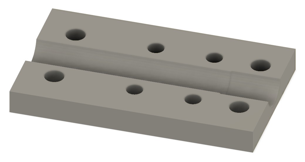
While a 3D model defines the geometry of a component, it rarely communicates every detail needed to manufacture the part correctly. Surface finishes, tolerances, materials, heat treatments, welding instructions and assembly notes are often missing from the CAD model itself.
“But won’t the machine shop figure it out? Isn’t that their job?”
In a word “no”, let me explain. Quoting accurately takes time, more than you might think. Planning fixturing, tool paths, purchasing speciality tooling, quotes for stock, this list goes on. A busy machine shop may have one or more people whose entire role is quoting, their salary is being spent on dealing with your enquiry.
Sending your enquiry to a machine shop is akin to sending your C.V. to a prospective employer. Much like a recruiter, the person dealing with your enquiry is under pressure to fill a gap with a good quality candidate that will benefit the business.
If your enquiry is going to lead lots of work trying to establish what you actually want (which they won’t get paid for), then it may end up at the bottom of the pile, ignored completely or you may be given a far higher price than you were expecting. The key to building a good relationship and the receiving the best prices is making sure that your enquiry is of good quality.
“But I told you in my drawing!”
A good technical drawing conveys exactly what you want and also forms part of the contract between you and your supplier. If something goes wrong and parts are not as expected, the first place the manufacturer will look is the drawing. If you have missed off some key information, if you only supplied a 3d model and at best a verbal description of what you wanted then you may have a tough time having parts re-made at the supplier’s expense.
Technical drawings remain the universal language of engineering.
Whether you’re manufacturing a single prototype or producing thousands of components, accurate engineering documentation ensures everyone involved—from designers and machinists to inspectors and assembly technicians—is working from the same specification.
At Profin H.D., we produce comprehensive technical drawing packages that allow components to be manufactured accurately, repeatedly and efficiently.
The Difference Between a CAD Model and a Technical Drawing
A 3D CAD model shows what a component looks like.
A technical drawing explains how it should be manufactured.
Think of the CAD model as the picture, while the engineering drawing is the instruction manual.
A complete technical drawing typically includes:
- Overall dimensions
- Critical tolerances
- Hole sizes and positions
- Thread specifications
- Surface finish requirements
- Material specification
- Heat treatment
- Welding symbols
- Geometric tolerances (GD&T)*
- Datum references
- Notes for manufacturing and inspection
Without this information manufacturers are forced to make either assumptions or enquiries. It stands to reason that both can be expensive.
*GD&T stands for Geometric Dimensioning and Tolerancing, an international symbolic language used on engineering drawings and 3D computer models to define the exact size, shape, orientation, and location of part features.
Why Accurate Drawings Reduce Manufacturing Costs
One of the biggest misconceptions in engineering is that producing detailed drawings adds unnecessary time.
The opposite is true. Technical drawings for manufacturing save everyone time!
Detailed documentation saves money throughout the manufacturing process by reducing:
- Design queries
- Production delays
- Programming errors
- Machining mistakes
- Inspection failures
- Assembly problems
- Scrap material
- Rework
When every feature is clearly defined, machinists can manufacture components with confidence, inspectors know exactly what to measure, and customers receive parts that meet specification first time.
Better Communication Between Everyone Involved
Modern engineering projects often involve multiple companies.
A product may be:
- Designed by one company
- Machined by another
- Surface treated elsewhere
- Assembled by a fourth supplier
- Installed by the customer
Technical drawings for manufacturing provide a common language that every supplier understands.
This dramatically reduces misunderstandings and ensures consistency throughout the supply chain.
Why Assembly Drawings Are Just as Important
Manufacturing individual parts is only half the story.
Assembly drawings show how every component fits together.
They typically include:
- Exploded views
- Item numbers
- Bill of Materials (BOM)
- Fastener information
- Assembly sequence
- Torque values
- Notes for installers
Without assembly documentation, even perfectly manufactured components can be assembled incorrectly.
The Role of 3D Models
3D CAD models have transformed product development.
They allow engineers to:
- Visualise products before manufacture
- Detect component interference
- Check clearances
- Simulate movement
- Produce realistic renderings
- Create exploded assemblies
- Generate CNC toolpaths
- Produce technical drawings automatically
However, they work best when used alongside detailed engineering documentation—not instead of it.
Supporting CNC Machining
CNC programmers rely heavily on technical drawings.
Accurate drawings provide:
- Critical dimensions
- Tolerance zones
- Datum positions
- Inspection points
- Surface finish requirements
- Thread details
Without this information, programming becomes slower and more prone to mistakes.
Clear documentation also helps reduce machine setup time and improves repeatability during production.
Supporting 3D Printing and Prototyping
Even when producing prototypes, technical documentation remains valuable.
Drawings allow designers to:
- Record design revisions
- Compare prototype iterations
- Identify manufacturing changes
- Specify test requirements
- Communicate modifications
As prototypes evolve into production components, this documentation becomes increasingly valuable.
Supporting Quality Control
Inspection begins long before a component reaches the quality department.
Every measurement is taken directly from the engineering drawing.
Technical drawings define:
- Which dimensions are critical
- Acceptable tolerances
- Surface finish limits
- Inspection methods
- Datum references
Without clear drawings, inspection becomes subjective.
Good documentation removes uncertainty.
Common Mistakes That We See
At Profin H.D., we regularly receive customer drawings that contain avoidable problems.
These include:
- Missing tolerances
- Undefined materials
- Incorrect thread callouts
- Conflicting dimensions
- Missing section views
- Incomplete notes
- Over-dimensioning
- No revision history
Correcting these issues before manufacturing saves both time and money.
Why Work with Profin H.D.?
If you don’t know how to create a technical drawing don’t worry, we can do that for you. The good news is that the cost of doing so will be a drop in the ocean, compared to what it could save you if you press ahead without a drawing.
At Profin H.D., we don’t simply create CAD models—we create complete manufacturing documentation. The cost of producing
Our design packages can include:
- Professional 3D CAD models
- Fully dimensioned engineering drawings
- Assembly drawings
- Exploded views
- Bill of Materials
- Manufacturing drawings
- PDF documentation
- STEP and native CAD files
- Revision control
- Design for Manufacture (DfM) recommendations
Whether you’re developing a new product, replacing an obsolete component or preparing for production, we ensure your documentation is ready for manufacture.
Final Thoughts
The quality of your manufacturing documentation directly affects the quality of your finished product.
Well-prepared technical drawings reduce errors, improve communication and lower manufacturing costs while making production significantly more efficient.
A detailed drawing package is an investment that continues to pay for itself throughout the life of a product.
If you’re looking for professional CAD design, engineering drawings or complete manufacturing documentation, Profin H.D. can help turn your ideas into production-ready designs.
Contact UsOr why not book a consultation?
Book a ConsultationFrequently Asked Questions
Why do manufacturers still need technical drawings if they have a 3D CAD model?
A CAD model defines the shape of a component, but technical drawings provide essential manufacturing information such as tolerances, materials, surface finishes, thread specifications and inspection requirements.
What file formats should I provide to a manufacturer?
The best approach is to supply both a 3D CAD model (such as STEP) and fully dimensioned PDF engineering drawings.
Can Profin H.D. create drawings from an existing part?
Yes. We can reverse engineer existing components and produce professional CAD models and manufacturing drawings suitable for CNC machining or production.
What is an assembly drawing?
An assembly drawing shows how multiple components fit together and often includes an exploded view, Bill of Materials and assembly instructions.