
Creating a CAD model is just the first step in bringing your product idea to life, you have to ensure that you don’t make a costly CAD mistake. While it may look perfect on your screen, not every CAD design is ready for production. Sending a model to a manufacturer that hasn’t been optimised can lead to delays, higher costs, and even scrapped parts. At Profin H.D., we help clients take their CAD files from concept, to manufacture-ready, with minimal hassle. Here are the five most common mistakes engineers and designers make — and how to avoid them.
1. Over-Complex Or Difficult to Produce Geometry
The mistake: Your CAD model is detailed and precise — but too complex for the intended manufacturing process. Small fillets, intricate patterns, or overly thin walls can be impossible to machine or print reliably or difficult/impossible to make.
Why it matters: Complex features may require custom tooling or additional setup, increasing lead times and costs.
If you keep receiving quotes that are much higher than you had hoped or worse still you are being ignored or that manufacturing businesses are declining to quote, then over-complex geometry might be the issue.
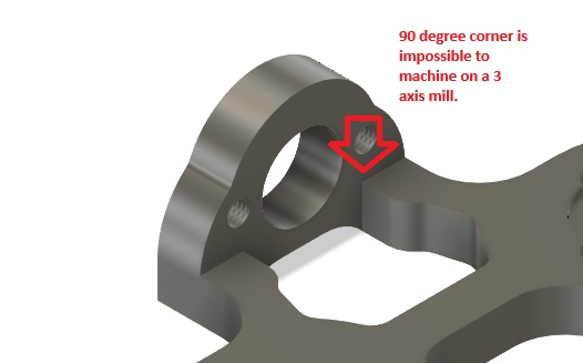
Below is an example of such a part that we were asked to make. The 90 degree corner is impossible to machine on a 3 axis milling machine as there is no access for a milling cutter to produce this feature. Whilst there are ways to make it such as wire EDM, this will significantly add to the cost of production. By adding a small radius into this corner, say 3mm, this feature could be milled using a 6mm cutting tool. The result would be that the cost decreases massively and a stress riser would be eliminated meaning a stronger part. There was in fact, no reason for the 90 degree corner to be present on this part.
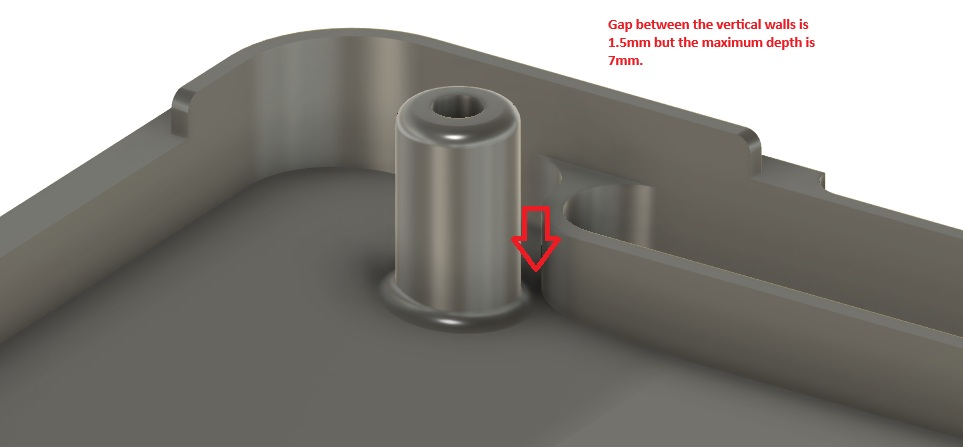
In this next example we were asked to machine the following part from aluminium in one piece. In this case the minimum gap between the vertical walls is 1.5mm (less for the fillet at the base of the vertical boss) but the total depth is 7mm. This means the milling cutter used would need to be under 1.5mm in diameter and the flute length 7mm or greater. This is problematic for chip clearance and tool rigidity.
Standard milling cutters have a maximum cutting depth of 2.5 x diameter. There are long series milling cutters available 4 or 5 x diameter the tool reach would need to be over 23mm to clear the vertical threaded boss which is way too much for a sub 1.5mm milling cutter.
What do you need to do to avoid this CAD mistake?
Profin H.D. tip:
- Simplify non-critical details without compromising functionality.
- Consider the limitations of your chosen manufacturing process (CNC, 3D printing, laser cutting). Think carefully about tool access and tolerance limitations.
- Discuss features and tolerances with your manufacturer early. Bear in mind that if you are going straight to manufacture with a machine shop, they may not have time to walk you through why your part cannot be made. They may just decline to quote instead. If you have an idea but you are not sure how to implement it we offer product development services and we can design the part for you.
2. Missing Tolerances or Thread Specifications
The mistake: Your model doesn’t specify tolerances or thread specifications, so you need to supply an annotated drawing to ensure that you get the part you were expecting.
Why it matters: Tolerances determine whether parts fit, assemble correctly, and function as intended. Missing thread and tolerance specifications can lead to costly rework.
We receive many enquiries where no drawing has been supplied, usually just a stp. file or an stl. file. If however you don’t supply a drawing the manufacturer won’t know if a hole is threaded on your 3d model (unless you have modelled the thread also) and it may take several emails back and forth to establish your requirements. The machining industry is a highly competitive one and machine shops really don’t have time to figure out your requirements if you haven’t already listed them.
Worse still you could end up with a part that doesn’t function or fit as anticipated.
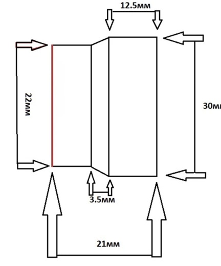
If you don’t specify tolerances then the manufacturer may just specify a general tolerance of +/- 0.3mm or 0.2mm in their quote. If you were then to provide a purchase order for that quote, then the mistake is on you as the customer and the manufacturer is unlikely to remake them at their expense. Remember that your drawing, the quote and the purchase order form the contract between both parties.
If you find that a part doesn’t fit and you say to the manufacturer that the tolerance or size should have been “XX” the first thing they will say is “well, your drawing didn’t say that”!
What do you need to do to avoid this CAD mistake?
Profin H.D. tip:
- Always supply a drawing and add dimension tolerances and thread details.
- Use standard thread types (metric, UNC/UNF) where possible – see our blog post on thread standards for more help.
- Reference fit classes (e.g., H7/G6) for critical components.
3. Using Multiple Datums And Different Units of Measurements
The mistake: referencing features from multiple datums.
Why it matters: Using multiple datums can introduce error in feature position.
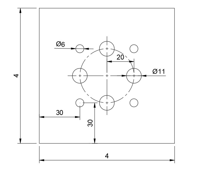
In the above sample we can see a simple aluminium plate that was to be profiled by a water jet machine. The plate was then to have 8 holes drilled, 4 of which should have been tapped for m6 screws.
Aside from the fact that the m6 threads aren’t mentioned you will note that they are referenced from the edge of the plate. The 4 x 11mm holes are however, referenced from the centre.
As the plate will not be exactly to size (there is no such thing as exact in machining) the 6mm hole position will be off relative to the 11mm holes by however much under or over sized the plate is. If you are having a plate profiled by laser or waterjet you can expect a tolerance of +/-0.2mm or 0.3mm.
The plates themselves should have been 100mm, though they are listed as “4” (which was supposed to be inches whilst the remaining dimensions were mm). However 4 inches equates to 101.6mm, so again the 6mm tapped holes would be out of position.
What do you need to do to avoid this CAD mistake?
Profin H.D. tip:
- Use 1 datum, in this case with a profiled plate where the final dimension is not yet known and the edges/overall dimension are no critical. Reference all features from the centre on profiled plates.
- Use the same units of measurements – metric or imperial.
Final Thoughts
Preparing a CAD model for manufacturing and avoiding a CAD mistake doesn’t have to be stressful. By avoiding these three common mistakes, you can save time, reduce costs, and improve the quality of your final parts. At Profin H.D., we specialise in taking CAD models from concept to production-ready, ensuring every file we receive is optimised for CNC machining, 3D printing, or laser cutting.
Next Step: Got a CAD model that needs checking? Send it to us today for a professional review — we’ll make sure it’s production-ready and ready to save you time and money.
If you need help we can produce a drawing for you.