In today’s highly competitive manufacturing landscape, design for manufacture (DFM) is no longer optional—it’s essential. Particularly in the realm of machined components, understanding the manufacturing process early in the design phase can mean the difference between a successful product and a costly mistake.
While Computer Numerical Control (CNC) machines offer incredible flexibility and precision, they are not limitless. Some parts, due to geometry or complexity, are either extremely difficult or impossible to produce on a conventional CNC lathe or mill—unless designers take manufacturing constraints into account from the outset.
In this article, we’ll delve into the principles of design for manufacture, especially as it relates to CNC machining. We’ll explore real-world examples of challenging parts, highlight why some designs break conventional CNC norms, and compare how DFM varies across industries like aerospace/space exploration at one end of the spectrum and consumer based automotive manufacturing at the other. The objectives and budget of a project can influence how DFM is applied.
What is Design for Manufacture (DFM)?
Design for Manufacture (DFM) is a product design approach that optimises a part or assembly for ease of manufacturing. It considers factors like:
- Machine capabilities.
- Tooling access.
- Material selection.
- Tolerances.
- Surface finishes.
- Setup and fixturing.
The goal is to reduce production costs, improve quality, and accelerate time to market, without compromising design intent.
In CNC machining, failing to consider DFM can lead to:
- Unnecessary complexity
- Longer cycle times
- Excessive tool wear
- Multiple setups
- Part rejection due to unachievable tolerances (very common, engineers may find that suppliers decline to even quote).
The above 5 points will almost always increase the cost of a project, if you are at the consumer end of the market an incorrect approach can kill a project before you even have the first prototype in hand.
Parts Difficult or Impossible to Machine on Conventional CNCs
While modern 5-axis CNC machines have broadened manufacturing capabilities, many shops still rely on 3-axis mills and 2-axis or live-tooling lathes. Here are some examples of parts that pose significant machining challenges on these platforms. Whilst these issues may seem obvious or exaggerated, these are very similar to designs we have received:
1. Internal Undercuts in Deep Cavities
Problem: Internal features such as undercuts deep within a cavity are notoriously difficult to reach using standard tooling.
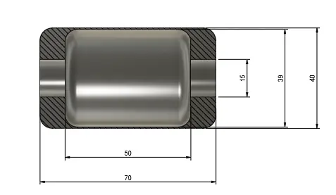
Why it’s difficult:
- Tool length-to-diameter ratios become unstable.
- Chip evacuation is poor.
- Coolant access is limited.
- Tolerances are hard to maintain due to deflection.
In the above example we have a 15mm diameter hole through the part, which means a boring bar needs to be smaller than this.
However generally a boring bar should stick out usually 3-5 x it’s diameter maximum (there are expensive exceptions), in addition to this the actual shank diameter of the boring bar will be smaller than 15mm to allow for tooling reach.
So even if the shank of the tool was to touch the 15mm internal I.D., the cutting tip would have to extend a further 11.5mm to achieve the 39mm dimension, leaving only 3.5mm for the boring bar shank before the tool would be too big to go through the 15mm.
Even if we could reach the internal diameter the part will quickly fill with chips during machining, resulting in chip re-cutting, poor finishes and potential damage to the part/tool. The surface being machined may also be starved of coolant.
Alternative Approaches:
- Use of custom extended tools and lathes with an additional tool post axis (expensive).
- Re-design the component so that it is made from multiple parts.
- Consider additive manufacturing or possibly fabrication (sheet metal/welding) as a re-design route.
2. Thin-Walled Components with High Aspect Ratios
Problem: Parts with extremely thin walls and tall profiles vibrate and deflect during machining.
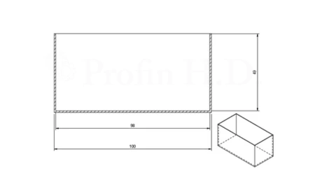
Why it’s difficult:
- Machining forces cause vibration, which can in turn lead to chatter. The walls on this aluminum box are just 1mm thick and the part is 50mm high. Aside from the fact that we are wasting a massive amount of material and machining time the part will vibrate when we approach the finished dimension.
- Chip evacuation won’t be ideal, even with high pressure flood coolant, chip re-cutting is likely.
- You can’t mill square internal corners. Milling cutters generally have a cutting length of around 2.5 times diameter as standard. Even with an extra long series cutters of say 10mm diameter with a flute length of 50mm will still be left with a 5mm radius in the internal corners.
- Maintaining consistent wall thickness is difficult and the material will deflect away from the cutting tool more at the top of the part than it will at the bottom..
Alternative Approached:
- Re-design the part with thicker walls and a radius in the corners.
- If tight tolerances and square corners are required consider EDM.
- Fabricate the part from sheet metal.
3. Complex Organic or Lattice Geometries
Problem: Freeform or lattice structures like those used in lightweight aerospace components are nearly impossible to machine conventionally.
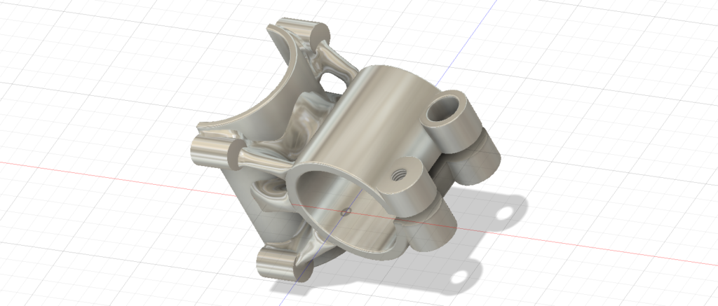
Why it’s difficult:
- No straightforward tool path.
- Multi-axis coordination is often needed.
- Internal channels or voids are inaccessible.
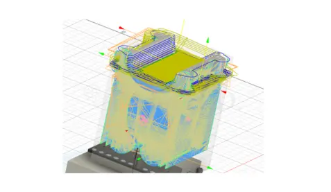
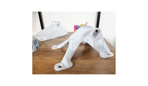
So the part pictured above and below is an “organic bicycle stem” designed to show case the benefits of additive manufacturing/3d printing. Whilst this part is machinable and was designed so that all features can be reached with a 5 axis milling machine and a 4mm cutter, the part would be very expensive.
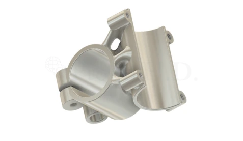
As you can see below the tool paths to mill this part are many in number. It took almost 3 hours to set up the tool paths using CAM software for a 5 axis milling machine and another 50 minutes was spent watching and verifying the simulation.
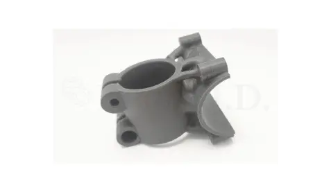
Whereas the setup time for 3d printing was less than 2 minutes and less than 4 minutes labour total to print the part. Granted, the print below was in PLA (plastic), but as we have touched upon in a previous article metal 3d printing is now very accessible. Even so for the modest cost of printing this part in plastic, it is a worthwhile exercise as it will allow you to hold and fit a physical part.
Here is an example of a 3d printed metal part at Manchester University:
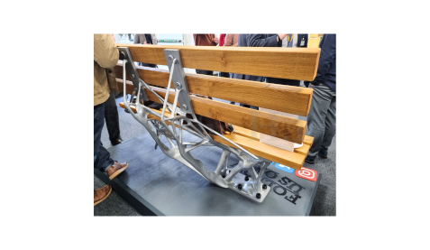
This is a metal bench at Manchester University – and you can sit on it!
Best Solution:
Additive manufacturing with post-machining for mating features or critical surfaces.
4. Deep Internal Threads
Problem: Internal threads that extend several diameters into a blind hole.
Why it’s difficult:
- Tool reach is limited.
- Thread quality suffers at depth.
- Risk of tap breakage increases.
DFM Tip:
Keep thread lengths to 1–1.5 times the major diameter. For deeper engagement, consider a nut/bolt redesign.
5. Parts Requiring Multiple Non-Coaxial Machined Faces
Problem: Complex geometries that require operations from multiple orientations can demand multiple setups, increasing the chance of error.
Why it’s difficult:
- High-precision alignment required between setups.
- Tool paths may not be reachable from single orientation.
- Fixtures become complex and expensive.
Remedy:
Design parts with datums aligned to a single coordinate system or reduce feature count on a single part by splitting into multiple parts.
Industry-Specific DFM: Aerospace vs. Automotive
Aerospace & Space Exploration
- Budget Tolerance: High. Components are typically produced in small quantities with generous budgets.
- Material Constraints: Exotic alloys (e.g., Inconel, titanium) are common due to heat resistance or weight constraints.
- Tolerance & Quality: Ultra-high precision required. Often in the micrometer range.
- Machining Freedom: Complex 5-axis setups, hybrid manufacturing, and additive processes are acceptable and often encouraged.
Common Design Practices:
- Integrated multi-functional components to reduce weight.
- Use of isogrid or lattice structures.
- High use of post-machining to bring additively manufactured parts into final spec.
DFM Strategy:
- Leverage advanced CAM simulation early.
- Involve manufacturing engineers in initial design.
- Accept longer lead times in favor of performance.
Consumer Automotive
- Budget Tolerance: Very low. Components must be cost-effective at high volumes.
- Material Constraints: Focus on machinability and cost—steel, aluminum, and plastics are common.
- Tolerance & Quality: Balanced with cost. Often ±0.1 mm is sufficient.
- Machining Freedom: Mostly 3-axis machining and turning. Automation and single-setup strategies preferred.
Common Design Practices:
- High use of standard fasteners and components.
- Modular assemblies to allow rapid manufacturing.
- Emphasis on DFM and DFA (Design for Assembly).
DFM Strategy:
- Avoid features that require custom tooling.
- Design parts that nest or align with minimal fixturing.
- Emphasize symmetry for setup repeatability.
DFM Tips for Machining Success
Whether you’re designing for satellites or sedans, here are some universal DFM tips:
1. Minimise Reorientations
Design parts that can be fully machined in one or two setups. This improves accuracy and reduces labor and the risk of introducing error.
2. Avoid Sharp Internal Corners
End mills are round, and internal corners need radii. Design accordingly to avoid unnecessary EDM or specialized tools.
3. Standardize Hole Sizes
Use hole diameters that match standard drill sizes to reduce cycle time and tool changes.
4. Design for Tool Access
Ensure that all features can be reached with common end mill sizes and angles (e.g., 90°, 45°). Avoid features that require undercut tools unless absolutely necessary.
5. Consider Material Removal Volume
Avoid designing parts that require removal of massive amounts of material. Instead, consider casting or additive-first strategies.
When Machining Isn’t the Best Solution
Machining isn’t always the right path—especially when dealing with:
- Hollow geometries with internal channels (use additive).
- Very high volume parts (use injection molding or die casting).
- Very hard or brittle materials (consider sintering or grinding).
The key is to match the design intent with the most efficient manufacturing process—which sometimes means pivoting away from machining altogether.
Conclusion: Design for Manufacture is a Mindset
The concept of design for manufacture is about embracing constraints—not as limitations, but as guidelines for efficient, elegant design.
In high-budget, low-volume industries like aerospace and space exploration, you can afford complex setups, specialized machines, and multi-step processes to achieve perfection. In contrast, automotive demands DFM discipline to ensure repeatability, speed, and affordability.
Either way, success starts at the design table. By understanding what CNC machines can and can’t do—and adjusting designs accordingly—you ensure a smoother transition from concept to component.
Call to Action
If you’re working on a new component design and indeed Design for Manufacture, take a moment to consult your machinist or manufacturing partner early. Better yet, bring them into your design review process. It could save a lot of money and weeks of delay.
Need help optimising your design for machining? Contact us for a free DFM consultation and take the guesswork out of production.
